
Septic Pump Wiring Diagram Free Wiring Diagram
How to Wire a Double Float Pump Switch R.C. Worst & Co., Inc. 75.9K subscribers Subscribe Subscribed 61K views 4 years ago SJE Rhombus Products Chris shows you how to correctly wire the.

Septic Pump Float Switch Wiring Diagram Free Wiring Diagram
0:00 / 5:18 Septic pump wiring Wholesale Septic Supply 2.3K subscribers Subscribe Subscribed 373 Share 73K views 5 years ago How to wire a septic pump..more.more Proper Float.

Bilge Alarm Wiring Diagram Easy Wiring
A typical septic pump wiring diagram consists of several key components: Pump Motor: This component pumps effluent from the septic tank to the drain field. The motor is linked to the power supply through the wiring connections outlined in the diagram.
3 float septic system wiring diagram FiezaFynnley
Aside from the septic pump, the septic controls often need wiring of their own. The controls — including the septic float switch — trigger the pump to activate when the water reaches a certain depth. The float switch ensures the pump only comes on when the float is in position. A licensed electrician will ensure all of the septic system.
Septic Tank Float Switch Wiring Diagram General Wiring Diagram
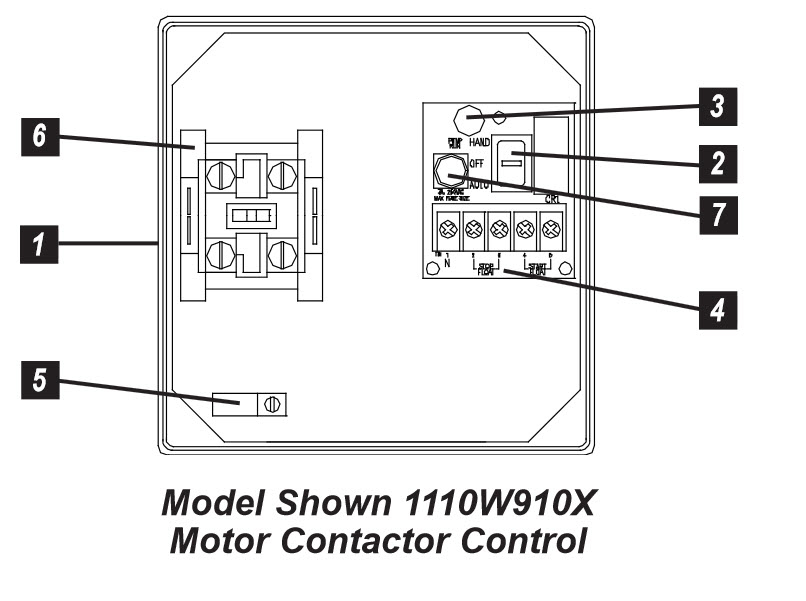
Do not service the pump or any electrical wiring in the pump vault without disconnecting the power at the circuit breaker and the fuse. The pump vault area is a hazardous area,. For septic tank float arrangement diagram, see drawing no. "EDW-FA-SSF-110". Note: Motors must have internal overload protection AL1-2 AL1 AL2. EDW-WD-SSF-104

Septic Pump Float Switch Wiring Diagram Free Wiring Diagram
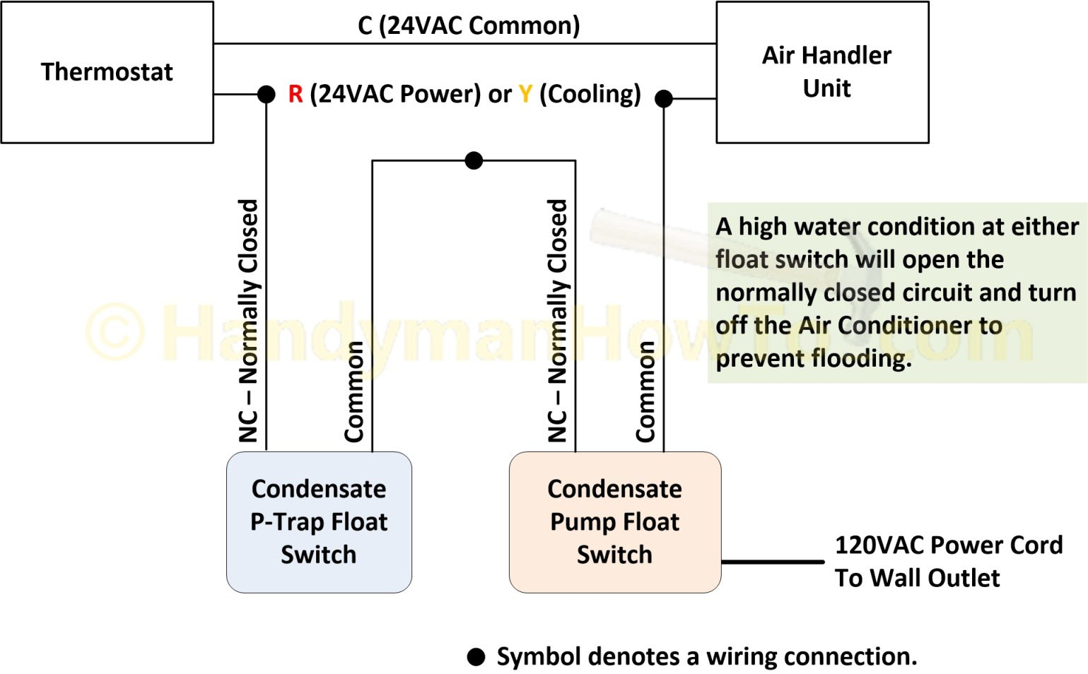
The wiring diagram for a septic tank float switch typically includes the switch itself, the pump, an electrical control panel, and a power source. The switch usually consists of two floats - a high-level float and a low-level float - connected to a control panel.

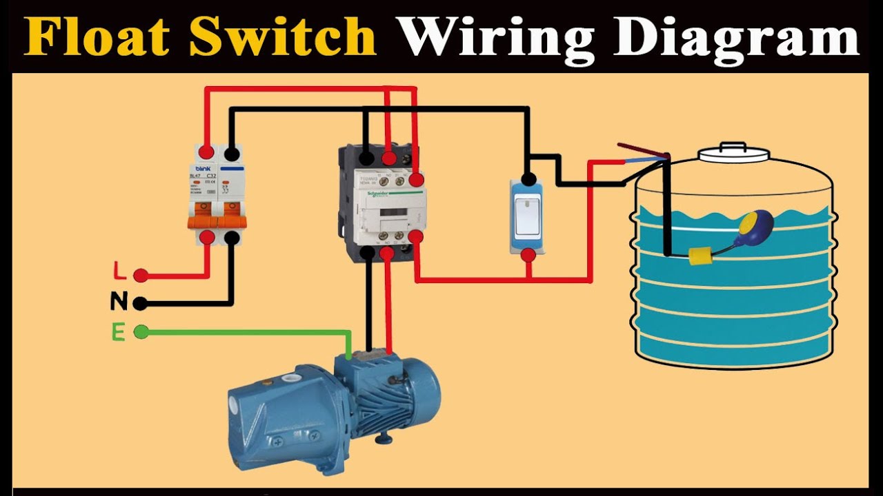
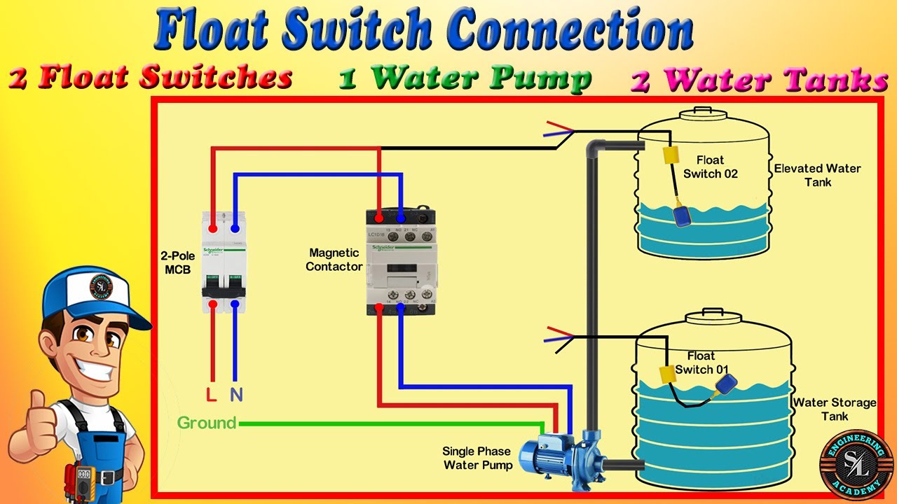
float switch wiring diagram for water pump YouTube
Fill the septic tank with water and observe if the float switch activates the pump at the appropriate level. Similarly, observe if the pump shuts off when the water level lowers. If any issues are detected, troubleshoot or seek professional help. Preventing Float Switch Problems Avoiding Excessive Pump Usage
Septic Pump Float Switch Wiring Diagram Gallery Wiring Diagram Sample
Electrical wiring leads for the grinder pump and septic pump alarm; Electrical disconnect box for the grinder pump system; Drain inlet: 4" PVC tank inlet for connection to building drains served by the pump; Sewage pump tank vent. The sewage grinder tank must be vented either directly or through the inlet pipe and within 4 ft. of the tank to a.
Septic Tank Float Switch Wiring Diagram Fresh Champion Pump Wiring
• Make sure this float switch is above the pump's minimum liquid level. Part 2. Adjusting Float Switch Settings Step 1. Check Float Switch Assembly. panel). • If you can't locate the wiring diagram, contact Orenco for a replacement. • For information on 3-pump or 4-pump systems, contact your distributor or Orenco. Step 2. Verify.

Septic Pump Float Switch Wiring Diagram Free Wiring Diagram
A septic pump float switch wiring diagram is a visual representation of the electrical connections between a septic tank, its pump, and the float switch. This diagram will provide a detailed overview of the components, the wiring, and the connections between the components. Understanding the Components of the Diagram

Septic Pump Float Switch Wiring Diagram Tank Fresh Amazing Gallery The
FLOAT SWITCH TYPES There are three types of float switches typically used on single phase pumps; single action, vertical and wide angle. Single action control switches can only be connected through a control panel. Connecting them directly to a pump will cause rapid cycling and may burn up the mo-tor, and/or the motor start switch and/or the.

Septic Tank Float Switch Wiring Diagram Free Wiring Diagram
Controls pumps up to 1 HP at 120 VAC and 2 HP at 230 VAC. Adjustable pumping range of 1.75 - 48 inches (4.45 - 122 cm) with increased pumping range up to 6 feet (1.8 meters) available. Includes standard mounting clamps and boxed packaging. Double Float® Pump Switch Diagram. For pump up or pump down applications as specified by part number.
Septic Tank Float Switch Wiring Diagram
Pump comes with float already. Should have instructions and a wiring diagram on how to connect it. If not then you need to contact the manufacturer. Float switch probably already connected to the pump wiring. Are you trying to use your old float switch. If so, it probably can't do it.
Sewage Pump With Float Wiring Diagram
Septic Tank Float Switches Septic Solutions offers a wide variety of float switches for septic tanks and lift stations. Pump duty float switches are designed to control a submersible pump turning it on and off automatically based upon the liquid level inside your pump tank.

️Septic Tank Wiring Diagram Free Download Gmbar.co
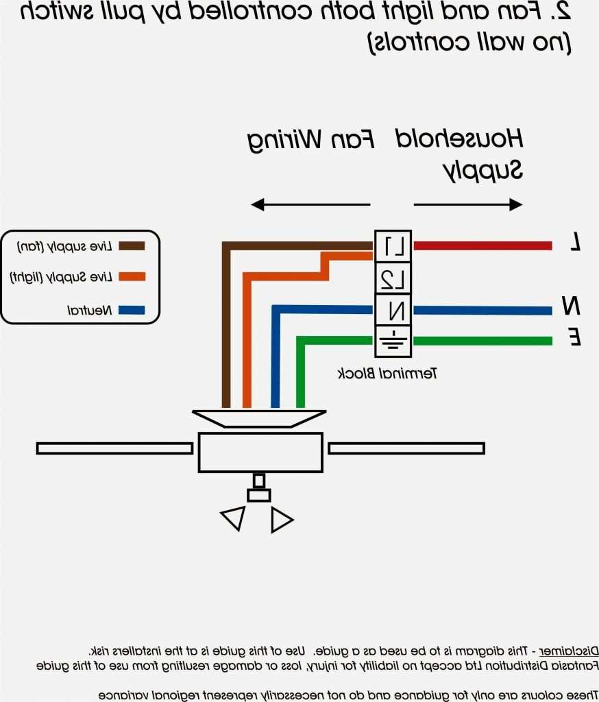
It shows what sort of electrical wires are interconnected and may also show where fixtures and components may be connected to the system. When and How to Use a Wiring Diagram Use wiring diagrams to assist in building or manufacturing the circuit or computer. They are also helpful for making repairs.

Septic Pump Float Switch Wiring Diagram Houses For Rent Near Me
Below is a diagram of what is described in the paragraph above. If you have any further questions, call 1-877-925-5132. Submersible pumps use float switches to perform automatic operation. The float switch moves with the water level in the tank and this determines when the pump turns on and shuts off.
